About
My capstone project was to design a testing device to democratize access to in-plane thermal conductivity testing by designing a cost-effective and reliable device using the Ångström method.
As a general overview, these are the key subsystems and what our final assembled system looked like:


Results
Our first test once the system was fully assembled resulted in 8% error between the measured value and the commonly accepted value in literature. Our second test, which ran 3x as long resulted in an error of 3.2%. This is significant as the system we designed was ~$3000, compared to existing industry solutions which are ~$100,000.
These incredible results got us one of the biggest awards given to capstone projects: Track Winner. My group and our advisor are pictured with our advisor below. From left to right: Myself, Charlie Schatmeyer, Jordan Abi Nader, Rocco Tropea, Aaron Leach, and Professor Erb.

Here are links to our final presentation, and final poster.
My Role
Electrical System:
Designed a custom PCB for PWM approximation of a sinusoid using MOSFETS controlled by a Raspberry Pi Pico (more details)
Feedthroughs:
Designed a thermal feedthrough to siphon excess heat away from the sample using ANSYS simulations to drive iterations. (more details)
Designed an electrical feedthrough to allow us to run power and signal wires through the wall of the vacuum chamber.
Software:
I wrote the interface between the raspberry pi pico and the website in python using asycnio, aiohttp, pyserial-asyncio. The bulk of my contributions can be found in this section of the repository. I also was a core contributor to the overall structure for HTTP requests and database structure.
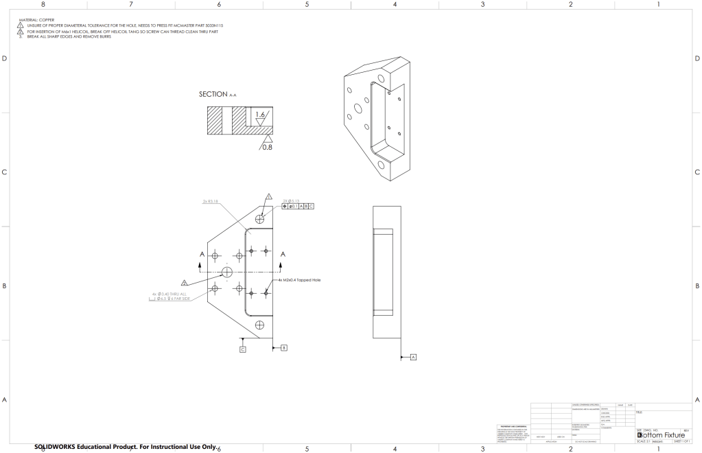
Machining Drawings:
In order to get parts machined by the machine shop on campus we had to submit drawings calling out any critical tolerances. Some of ours required GD&T and quick tolerance stack up calculations. Aaron Leach and I had the most experience with machining out of anyone in our group, so we contributed to the DFM of all components. In addition, I was responsible for making a majority of the drawings of the machined parts and doing the final checks on the ones I didn’t make.
More Details
Thermal Feedthrough
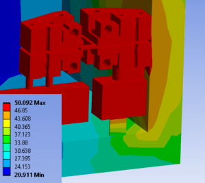
The thermal feedthrough was perhaps the most engineering intensive part of the project as it required many iterations and FEA simulations.
- First Iteration
- Using the wall of the vacuum chamber as a heat sink
- Very simple design
- Refined Design
- Using the wall of the vacuum chamber as a heat sink
- Acrylic vacuum chamber wall wasn’t siphoning heat fast enough
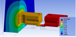
- Refined Design with Thermal Feedthrough
- Block of copper through a hole in the vacuum chamber
- Also provides the option to drill holes for liquid cooling if passive isn’t enough.
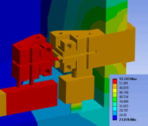
Although there were several iterations not pictured above, each thermal simulation guided the next. More photos and videos of the simulations I ran can be found in our engineering analysis presentation.
Electrical System Design
In order to do the sinusoidal control of thermal output I looked at using JFETs as voltage-controlled resistors, voltage controlled current sources, and more expensive signal generators. However, in the end, I settled on using a PWM approximation of a sinusoid using MOSFETs controlled by a Raspberry Pi Pico. The design was first proven on a protoboard.
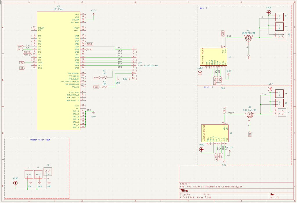

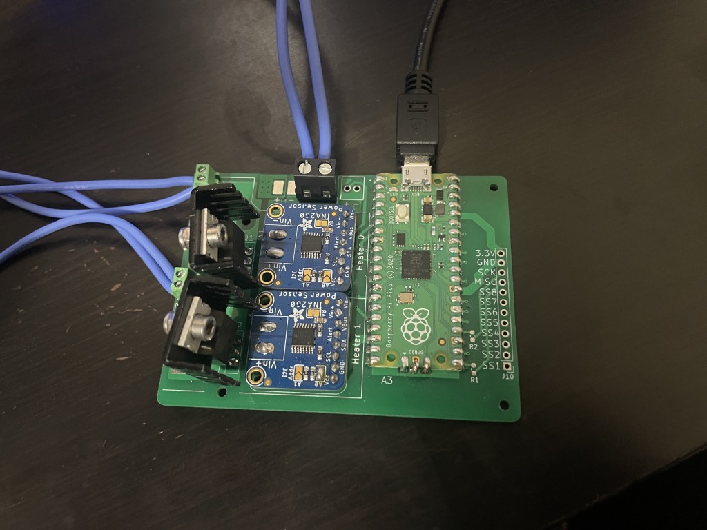
While the protoboard worked, all the wiring was messy and was annoying to assemble, so I decided to design a PCB; the design files can be found here.

Ångström Method
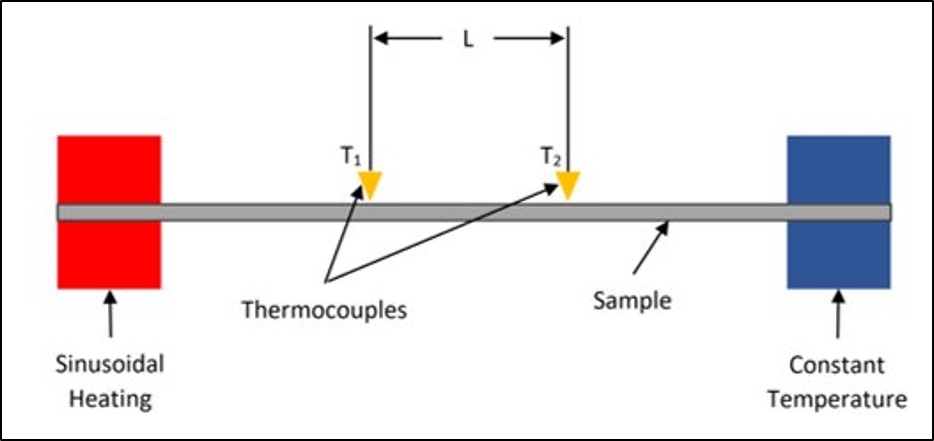
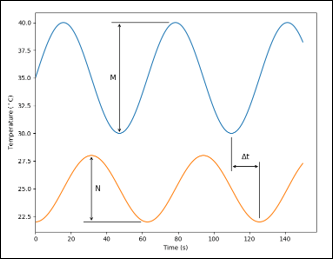
The Ångström method was the theoretical backbone of our capstone project and is described below:
A thin sample is heated sinusoidally on one end and kept at a constant temperature on the other end. Along the sample, 2 thermocouples with a known separation distance L record the temperature as heat travels across the sample. If heat moves 1-dimensionally through the sample, the amplitude and phase shift of the thermocouple measurements can be used to compute the thermal diffusivity of the sample material, which can then be used to calculate thermal conductivity.